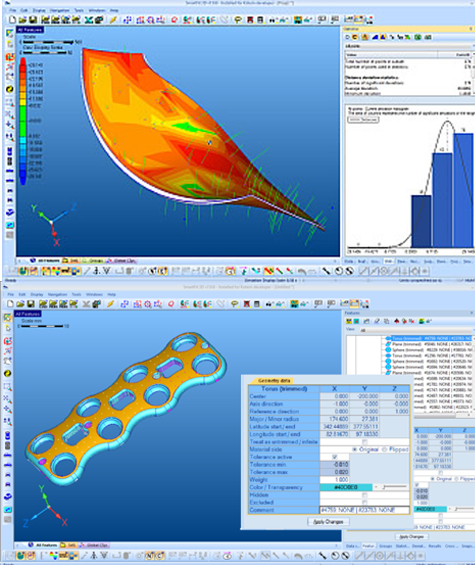
SmartFit 3D is an interactive software environment where measured data is analyzed, optimized, and compared to CAD and theoretical data.
SmartFit 3D starts working where your measuring tools leave off. This powerful, intuitive software accepts measured data from virtually any contact or non-contact inspection device, including Cmms, laser scanners, laser trackers, and video systems.
Data are compared to the nominal representation of a part (CAD model, drawings, nominal points) to optimize their positions. Intelligent best-fitting mathematical methods provide thorough analysis, optimization, and evaluation of conformance to form and location for 2D/3D rigid bodies and assemblies.
Data imported into SmartFit 3D can be optimized in “Point to Point” or “Point to Surface” mode. In “Point to Point” mode, the nominal coordinates of each measured point are explicitly defined and remain unchanged during the entire optimization process. “Point to Surface” mode represents the nominal part with a CAD model, while the nominal points are represented by the projected coordinates, which usually vary at each optimization step.
SmartFit 3D works with you to answer questions like these that impact your bottom line. Using advanced best-fit algorithms, your part is precisely evaluated against the nominal model to solve misalignment and location problems so that it can be repositioned for machining. The exacting SmartFit 3D process uses eight mathematical criteria to get the job done.
- Eight mathematical criteria for best-fitting – Least squares, Minimum Sum of Deviations, Mini-Max, Uniform Deviations, Minimum Standard Deviation, Tolerance Envelope and Tolerance Envelope Mini-Max
- Calculation with uncertainty information – best fitting can take measurements’ uncertainties into account if provided. Optimization algorithms will achieve the best solution, with all uncertainty zones put into tolerance
- Tools for forcing a solution by weighting, excluding or releasing points
- Calculation of basic geometric elements certified by PTB
- Cross-sectioning capability – allows creation of cross sections from high complexity freeform models, with analysis of errors in 2D
- Cross section can be included in reports or exported for further analysis
- Multiple error display modes, including color mapping, statistics, graphics snapshots and detailed point/error information
- “Point to Point” and “Point to Surface” working modes
- Built-in filters automatically invoked during measured data import
- Annotations and basic dimensioning capability
- Discrete reverse engineering, 2.5D and 3D mesh construction from point clouds
Copyright © 2021 OPG (Shanghai) Co., Ltd.
沪ICP备12031505号


