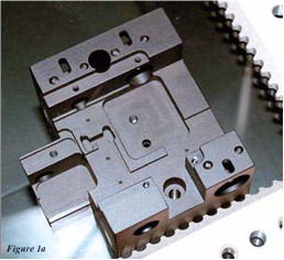
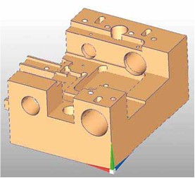
Multisensor metrology is a dimensional measurement on a measuring machine that utilises two or more different sensor technologies to acquire data points from features and surfaces of a part to perform more measurements than would be possible on a machine using a single sensor. Figures 1aand b show a complex machined part and its corresponding CAD model. Selection of sensors depends on the features to be
measured.
The design drawing shows what needs to be measured. The following series of illustrations show areas on a single part best measured by each sensor technology.
Note that the part has an assortment of holes and slots, surfaces at different depths, and some intricate detail.

Probe.Scan.Laser.Result
Assume the blue-highlighted edges in the CAD model in Figure 2b need to be measured to determine the relationship (distances) between them. Either of those edges can be assumed to be the intersection where perpendicular surfaces meet.
In such a case, a touch probe can collect data points on each of those perpendicular surfaces. The software then fits those sets of points to planes and intersects the planes. Those intersections represent those edges.
That through-hole and the edge radius complicate this otherwise straightforward process. Fortunately, it is possible to measure those edges directly with video. The edges appear to be parallel to the worktable and thus perpendicular to the optical axis of the video sensor.
Capturing Data
Figure 2a shows a video measurement of an arc segment on the actual part. Certain video tools can automatically follow an edge, collecting points even if it has changes in direction. This example also shows that each edge lies in a different plane yet they still can be measured with video.
On the same part, Figure 3b shows two areas in blue that form planes which must be parallel to each other. In addition, it is necessary to know how far each surface deviates from a plane (its flatness). The best sensor for this is a laser. Its focus point can be scanned across each plane acquiring point clouds of data.
Each set of data can be fit to a plane. Deviations from each plane can be measured. In addition, the relationship between the planes can be compared to determine their degree of parallelism. Not all lasers are created equal and this part has characteristics that make laser selection important.
Note the perpendicular surface between the two planes. Measuring the larger plane requires adequate working distance to avoid collisions with the higher surface. (See the laser spot and its path in the photograph of Figure 3a)
Measuring that plane close to the perpendicular surface may be a problem for some triangulation lasers since that surface may block either the incident or reflected light. Some Through-The-Lens (TTL) lasers can measure up to the base of the perpendicular plane.
This part also has some holes that are perpendicular to the top surface when the part is in this position. If we want to measure the perpendicularity of the cylindrical axis of one of these holes to the surface the hole is drilled into, a touch probe is the best tool for the job. As shown in Figure 4, points on the plane can be probed. Then a star probe can collect points along the cylinder walls. Those sets of points are fit to a plane and cylinder, respectively and their angular relationship measured.
Choose Wisely
All the measurements described can be performed on one multisensor measurement machine with the part in a single location. None of the sensors is best for doing all these measurements. Selecting the best sensor for each aspect of the total job depends on understanding what each does best.


